Hier finden Sie die Aussteller der EMV 2025. Die Ausstellerliste 2026 steht voraussichtlich ab Herbst 2025 zur Verfügung.
Schlöder GmbH

Adresse
Schlöder GmbH
Edisonstr. 6
85716 Unterschleißheim
Germany
Telefon+49 89 693142350
Fax+49 89 693142359
Entdecken Sie mehr von uns
Folgen Sie uns auf
Über uns
Schlöder GmbH has been developing and producing test and measurement technology in the EMC sector for 30 years. Thanks to our many years of experience, we have been able to adapt our products to the increased global requirements for manufacturer and industry certifications and manufacture innovative devices, always keeping the customer's requirements in mind. The development, construction and functional testing of the devices are carried out in Germany.
With a wide range of products, our particular strengths lie in the areas of
- ESD
- Burst/EFT Immunity
- Surge Immunity
- Conducted Immunity (DC - 400 MHz)
- Magnetic Field Immunity (DC - 26 MHz)
- Voltage Interruption
Our partners in the field of high-quality network and signal connection cables with very high immunity to conducted and radiated interference as well as innovative electronic components round off our portfolio.
Schlöder products stand for high quality and durability. With our products and innovations we are able to convince with an up-to-date and extensive assortment. But not only our product quality but also our comprehensive and competent service completes our offer.
- Service
Our aim is to provide our customers with a positive experience when working with Schlöder. Already at the inquiry we are your competent contact person who will advise you which products are suitable for your requirements and help you with the product selection with all necessary components. Also during the later installation we can support you with individual questions and instruct you with competent consultants. Every request will be handled quickly and without complications.
- Product quality
To be successful in the market, the product quality must be superior. This applies to the durability, the intuitive operability and the degree of innovation. Our claim as an EMC manufacturer is to offer our customers durable products that are designed to meet the respective standard and can be operated intuitively, even if they are only rarely used. Our EMC devices are developed and manufactured in Germany and are subject to constant development.
- Customer focus
Our customers appreciate us for offering the best fit solution. Our contribution to sustainability is that we also repair 25 year old equipment - as long as the required spare parts are available. You urgently need a replacement unit? Are you looking for a loaner device? You have questions about a specific standard? Please contact us and we will try to find a solution together.
- Value for money
Due to lean and efficient structures in production and sales we are able to create a convincing offer of product and service quality.
- Response time
Our in-house response time policy is 90/24, which means that on working days at least 90 % of enquiries are answered within 24 hours.
- Processing time
In the area of after-sales service, the processing time for calibrations and repairs is of great importance for our customers. Despite the excellent quality of our products, it is possible that repairs may be necessary after a longer service life. For factory calibrations and repairs, our target for processing time is max. 2 weeks. This means that the devices are quickly back for tests in your laboratory.
Keywords
- ESD
- Burst/EFT Immunity
- Surge Immunity
- Conducted Immunity
- Magnetic Field Immunity
Unsere Produkte

Test-Setup for medical equipment
IEC 60601-1-2 Ed. 4.1
IEC 61000-4-39
IEC 60601-1-2 is the international standard for testing medical equipment for electromagnetic compatibility (EMC). The latest update adds a new test due to more potential sources of interference in homes, offices (places where medical equipment may be used), and hospitals.
Request a quote now
Three common frequencies are: 30 kHz, 134.2 kHz and 13.56 MHz. For this test, reference is made to the IEC 61000-4-39 standard for testing of fields in close proximity. The IEC 60601-1-2 test setup can be used to generate these test fields.
The test equipment includes the CDG 7000-75-10 – 10 kHz - 250 MHz, 75 watt generator with amplifier (additional preamplifier depending on requirements), RF generator and 3x RF meter (monitored level, forward and reverse power) and the HELIA 7-MGA software. The system includes all cabling and HELIA 7 software necessary to meet the requirements of the standard.
Depending on the frequency range, different complete sets are available:
Required complete set for frequency range 9 kHz - 150 kHz:
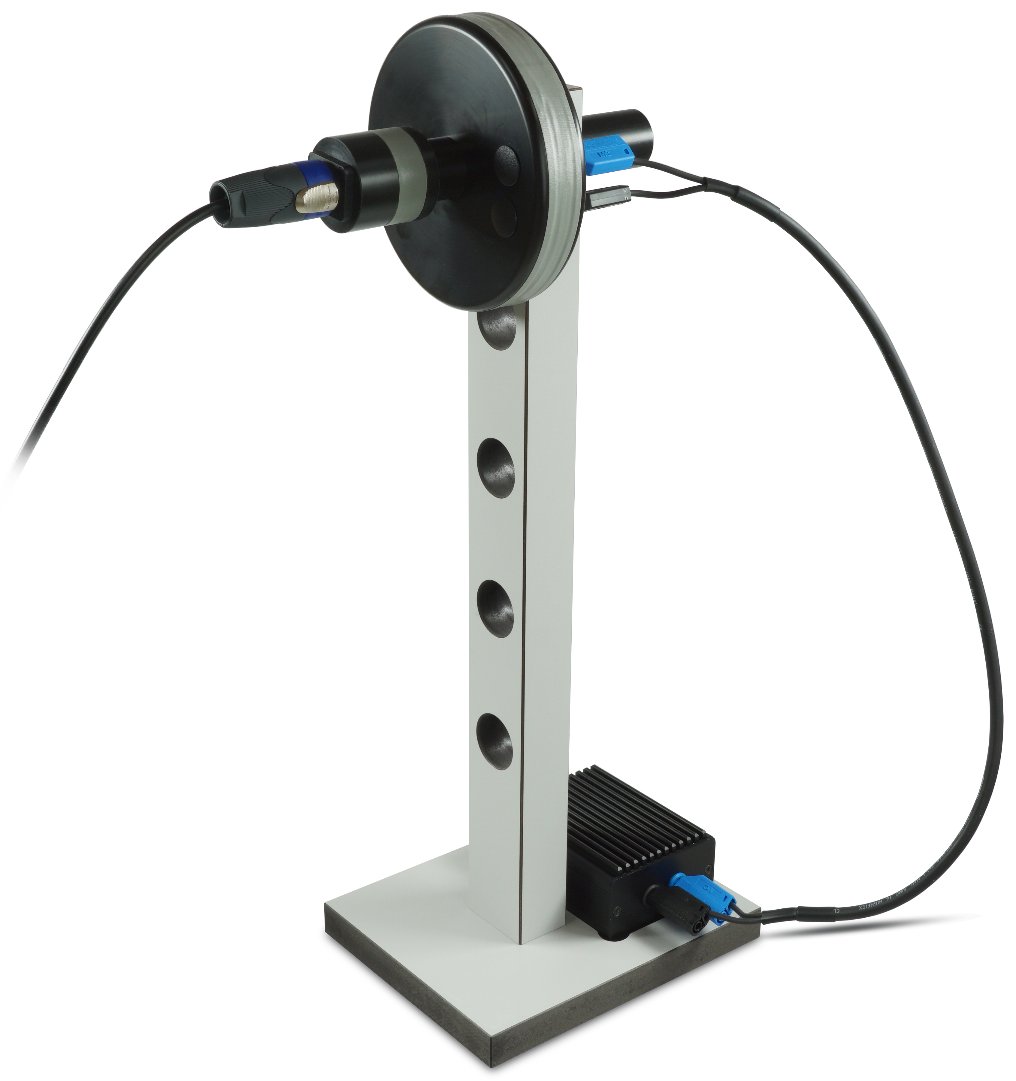
- MGA RL 120 – Radiating loop 120 mm as specified in IEC 61000-4-39 for 9 kHz-150 kHz, IEC / EN 60601-1-2 and MIL-STD-461 / RS101, 3 m cable
- MGA RL 120 NW – Matching network for MGA RL 120, matches loop to 50 Ohms of the CDG 7000 amplifier acc. to IEC 61000-4-39 and IEC / EN 60601-1-2 for Immunity to magnetic fields 9 kHz - 150 kHz
- MGA RL 120 Stand – Stand for MGA RL 120 for tests
- MGA LS 040 – Loop sensor 40 mm that attaches to MGA RL 120 at the correct distance of 50 mm
Required complete set for frequency range 150 kHz - 26 MHz:
- MGA RL 100-3– Radiating loop as specified in IEC 61000-4-39 and IEC / EN 60601-1-2 for 150 kHz – 26 MHz
- MGA LS 040-1– Loop sensor 40 mm that attaches to MGA RL 100-3 at the correct distance of 50 mm as specified in IEC 61000-4-39 and IEC / EN 60601-1-2
- MGA RL 100-3 stand – for tests in stronger magnetic field
In addition, one of the two adaptation networks/Pre Amplifier is required:
- MGA RL 100-3 NW-60601 – Matching network 60601 for MGA RL 100-3, matches MGA RL 100-3 to the IEC 60601-1-2 requirements
or
- MGA RL 100-3 NW-61000 – Matching network 61000 for MGA RL 100-3, matches MGA RL 100-3 to the IEC 61000-4-39 requirements
- PreAmp 150kHz-26MHz -4-39 - Pre Amplifier for tests according to IEC 61000-4-39

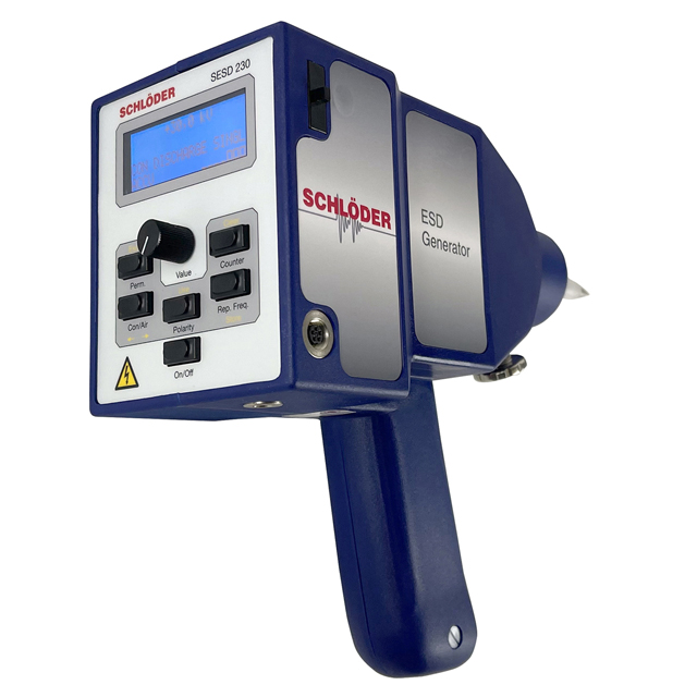
ESD Simulator SESD 230 | 30 kV
IEC 61000-4-2
The test generator SESD 230 simulates electrostatic discharge as defined in the standard IEC / EN 61000-4-2. Higher test levels can be set far beyond the standard limits.
Two test methods are used depending on the test specimen and test setup:
Air discharge (AIR) and Contact discharge (CON)
The test probes for air and contact discharge are included in the scope of delivery! Further models for special requirements are available in our extensive range of accessories.
The large display with easy-to-read digits shows the current operating status, all selected parameters and the actual discharge voltage during air discharge. The clearly arranged keyboard and automatic programmable test sequences enable intuitive operation.
The ESD gun does not require a base unit and can be operated via an in-built rechargeable battery or mains supply. The device has a user-friendly touchscreen, ergonomic design and remote control software. The functional design and optional remote control software ensure optimum handling at an excellent price/performance ratio.
Performance features:
- Air/ Contact discharge: up to 30 kV
- Output voltage: adjustable via potentiometer
- Holding time: >5 sec
- Pre selectable counter: 1 - 9999
- Discharge resistor: according to IEC / EN 61000-4-2
- Energy storage capacity: 150 pF ± 10%
- Discharge resistance: 330 Ohm ± 5%
- Weight ESD gun: approx. 1470 g
- Battery and mains operation
- Contact control for contact discharge
- Display of the actual discharge voltage during air discharge
- Automatic programmable test sequences
- Predefined standard test levels
- ‘Counter’ operation with / without automatic polarity changeIn a practical carrying case with accessories: 2 discharge tips (AIR/CON), Ground cable, Battery charger incl. cable
Accessories:
Like every product from Schlöder GmbH, the ESD simulators are complemented by a powerful portfolio of accessories to complete your test stations. Appropriate accessories are available for the SESD 230 for tests in accordance with IEC 61000-4-2.
- Horizontal coupling plane (HCP) - and vertical coupling plane (VCP)
- Earth cable
- ESD verification set, 4 GHz additionally with suitable transport case
- Test Tips for ESD
- Support arm with balancer and practical suspension hooks for hanging on the balancer
- Silicon sheet (IEC/EN 61000-4-2), table mats for ESD test stations
- ESD remote control software
Contact control:
The simulator has a "Contact control". When testing "CON" touches the test tip the surface of the EUT. When not contacted, will be no triggering of the pulse. The display shows "No contact". This ensures that at contact discharge actually occurs a discharge.

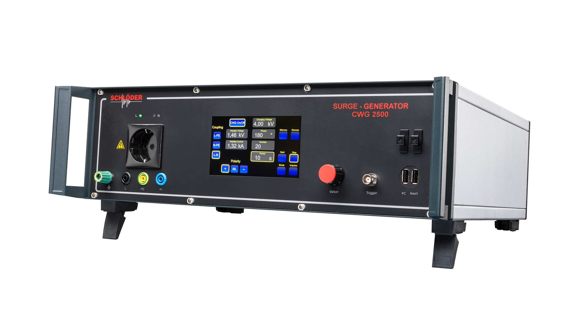
Surge / Hybrid Generator CWG 2500
IEC / EN 61000-4-5
The test generator CWG 2500 simulates high-energy interference pulses and is suitable for performing EMC tests on systems and systems in accordance with standard IEC/EN 61000-4-5.
The simple operation takes place via capacitive color touch display. All parameters are clearly displayed on the screen without nested menus and can be changed quickly by tapping and using a digital rotary encoder. The normative test levels 1,2,3 and 4 preprogrammed, additional test sequences can be stored by using the memory function.
The CWG 2500 can also be controlled by a PC via USB interface or optional fiber-optic interface.
Performance feature:
- Charging voltage: 0.2 - 4.4 kV
- Short-circuit current: 0.1 - 2.2 A
- At open circuit: generation of standard surge voltage waveform 1.2 / 50 µs, standard surge current waveform 8 / 20 µs
- Capacitive color touch display
- Charging time: < 10 sec
- Measurement "U" and "I" during pulse triggering
- USB, optional optical interface with fiber optic cable
- Memory function, recall test level 1-4, up to 32 memories
- Durable due to high-quality components
- Single-phase integrated coupling network
- Couple test pulses to supply lines of the test object
- Extensive range of accessories
- Optional: remote control via PC, EMC software
- Weight: approx. 18 kg
Measuring the pulse shapes:
The surge generator has 3 different internal measuring circuits for physically correct measurement of the surge pulses - L to N, L to PE and N to PE. The values for current and voltage are displayed; BNC outputs for current and voltage are available on the rear for oscillographic analyses.
Memory – Function:
All parameters can be easily and clearly set. Up to 32 settings can be activated directly by means of the memory button.

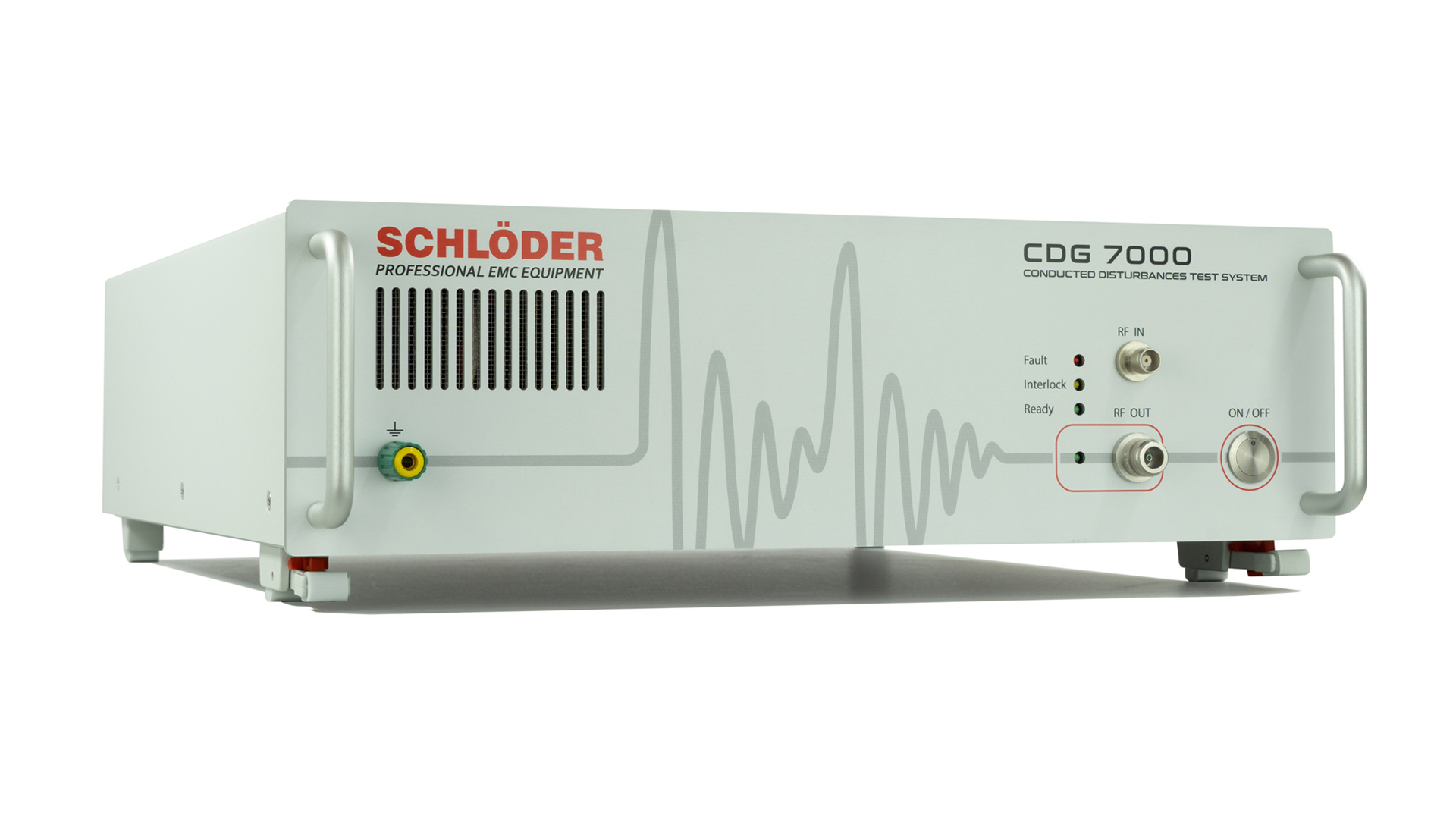
RF Generator CDG 7000 | Immunity | 10 kHz - 400 MHz
IEC / EN 61000-4-6
IEC 60601-1-2 Ed. 4.1 / IEC 61000-4-39
MIL-STD-461 CS114
ISO 11452-4
IEC 61326-3-2
NAMUR
The CDG 7000 is a new test generator for all standards for immunity to conducted disturbances and magnetic fields induced by radio-frequency fields, such as IEC 61000-4-6 - including BCI tests (ISO 11452-4). The CDG 7000 generates interferences as defined in IEC / EN 61000-4-6 - immunity to conducted disturbances induced by radio-frequency fields. The standard describes a test setup in which these high-frequency interferences can be influenced on a EUT without a complicated structure with antennas, field instrumentation and shielded rooms. By using coupling networks and coupling clamp's sine waves are induced directly into power and signal lines. The test object retains its original place in the device structure, so that the system can be tested in its overall function.
The versatile combination device includes
- an RF signal generator, an RF power amplifier, a 3-channel RF voltmeter and a directional coupler.
The test generator CDG 7000-75-10 in combination with our test sets is suitable for tests according to IEC 60601-1-2 Ed. 4.1 and IEC 61000-4-39.
The CDG 7000-E is another device that does not contain an internal RF power amplifier to allow customers to use flexible external amplifiers.
Performance features:
- Top price / performance ratio!
- The compact device consists of an RF signal generator, an RF power amplifier, a 3-channel RF voltmeter and a directional coupler
- Frequency range (signal generator) 4 kHz - 1200 MHz
- The RF generator for conducted and magnetic field tests is available in four different versions:
- CDG 7000-25: 100 kHz - 250 MHz, amplifier 25 W
Maximum test level: 10 V (15 V) with 80 % AM (without 6 dB)
Built-in directional coupler (200 W, 100 kHz - 500 MHz), with HELIA 7 - Basic USB, LAN software
- CDG 7000-75: 100 kHz - 400 MHz, amplifier 75 W
Maximum test level: 30 V (40 V) with 80 % AM (without 6 dB)
Built-in directional coupler (200 W, 100 kHz - 500 MHz), with HELIA 7 - Basic USB, LAN software
- CDG 7000-75-10: 10 kHz - 250 MHz, amplifier 75 W
Maximum test level: 30 V (40 V) with 80 % AM (without 6 dB)
Built-in directional coupler (200 W, 10 kHz - 400 MHz) with HELIA 7 - Basic USB, LAN software
- CDG 7000-E: Frequency range of the generator/power meter (4 kHz):
9 kHz - 1200 MHz, no integrated amplifier
Built-in directional coupler (200 W - optionally up to 500 W, 10 kHz - 1 GHz) with HELIA 7 - Basic USB, LAN software
- The included application software (HELIA 7 - Basic) enables extensive reporting functions and EUT monitoring, (HELIA 7 - BCI required for BCI testing)
- Simple expansion with external amplifier via 2nd generator output
- SCPI command set enables easy integration into own software systems
- Interfaces: USB, LAN, GPIB (option)
- Temperature measuring input, e.g. for monitoring and displaying the BCI clamp temperature
- Input for external pulse modulation
- Configurable, digital 8-channel user port
- Warranty 3 years
Helia 7:
We provide the test system from the factory with "Helia 7", an uncomplicated application software. This enables extensive reporting functions, as well as EUT monitoring. In addition, the package includes a self-test. And last but not least, you have the possibility to initiate automatic test sequences based on different standards. You can also use the "Direct Mode" to subject the EUT to further different tests. Integration into your own software systems is easy thanks to the integrated SCPI command set. If you want to perform additional BCI tests, the Helia-7 BCI software is available as an option. We have developed this program to enable you to control, analyze and document BCI tests. At Schlöder, service is a top priority. You therefore receive a three-year manufacturer's warranty and can contact customer service at any time if you have any questions.

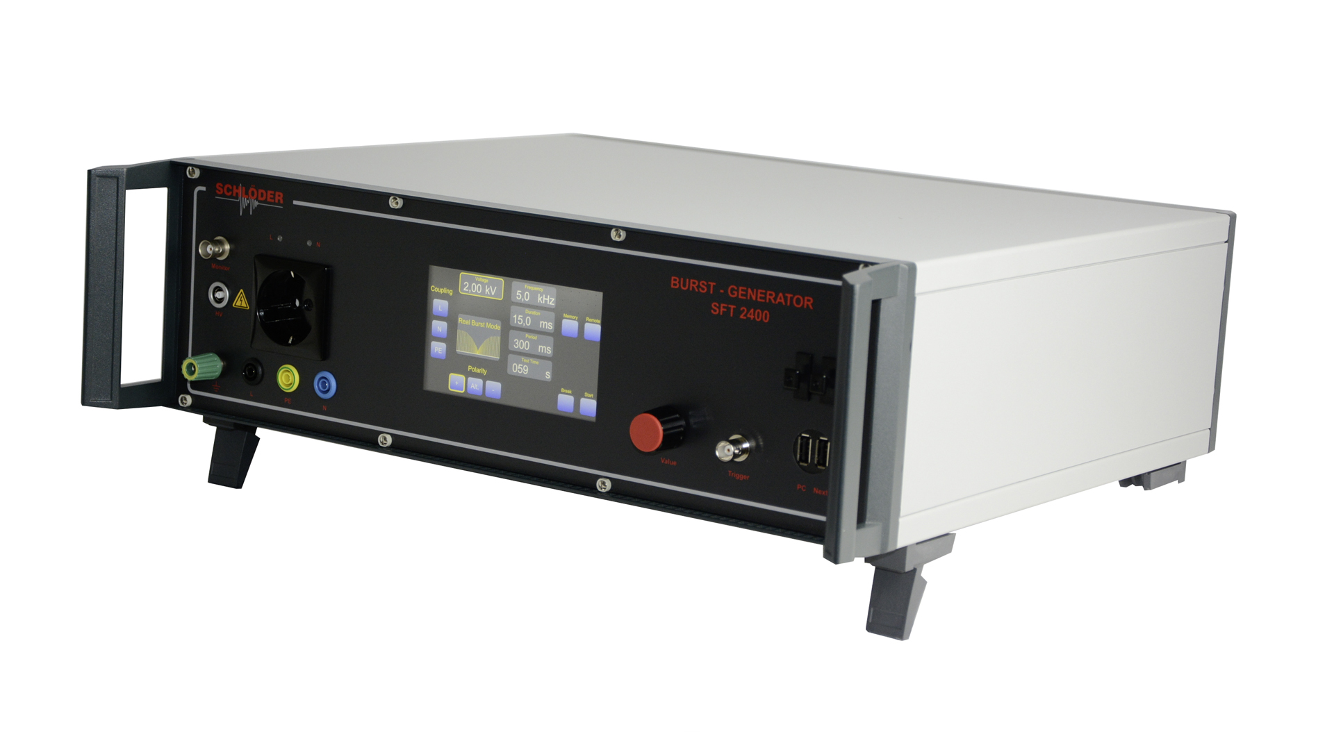
Burst Generator SFT 2400 | 125 kHz
IEC / EN 6100-4-4
The SFT 2400 with integrated coupling network simulates electrical fast transient (EFT) as defined in IEC 61000-4-4 standards. Due to very short rise time of 5ns, the individual pulses generate a broadband RF spectrum up to 300 MHz.
The simple operation takes place via a capacitive color touch display. All parameters are clearly displayed without nested menus and can be changed quickly by tapping and using a digital rotary encoder. The normative test levels 1, 2, 3 and 4 are programmed, additional test sequences can be stored via the memory function.
Performance features:
- Burst frequency: Single pulse up to 125 kHz
- Burst duration: 0.01 - 100 ms (limit parameters are automatically taken into account)
- Burst period: 10 -1000 (limit parameters are automatically taken into account)
- Pulse voltage: 100 V - 5000 V
- Polarity of burst packet: positive, negative, alternating
- Waveform according to IEC 61000-4-4: 5 ns / 50 ns
- Capacitive color touch display
- Max. Pulses / sec: 5000 (up to 2 kV), 3000 (up to 3 kV), 1500 (up to 5 kV)
- Max. Pulses / packet: 500
- Trigger: manual or external
- HV output: coaxial socket
- Monitor output: BNC, TTL level
- Interface: USB (virtual COM port)
Optional: optical (Toshiba LWL) - Internal single-phase coupling network
- Weight: 9 kg
Functionality:
All burst parameters can be changed during a burst test. This guarantees that it can be easily and continuously to detect the fault threshold of the specimen. An interruption of the test for a parameter change at the burst generator is not necessary.
Burst pulse in practice - Real Burst:
The pulse burst occuring in practice does not comply with the definition of the standard. Its physical properties are deviating against the standard definition. The generator SFT 2400 provides the user a variety of special features such as "Real Burst", which simulates the natural appearence of the Burst pulse or "Noise" can be simulated with the contact bounce.
Time accurate triggering:
To localisation of faults, it is possible to couple the burst pulse very accurately to a certain process time of the EUT. The burst pulse microsecond exactly triggered with a jitter of <25 ns.

