
Skip

On this page, you will find all exhibitors of EMV 2026. The exhibitor search provides you with a comprehensive overview of the participating companies and their products.
MPB Srl
Product: SEMS B- System for measuring the shielding efficiency of a shielded chamber

SEMS B- System for measuring the shielding efficiency of a shielded chamber

Description

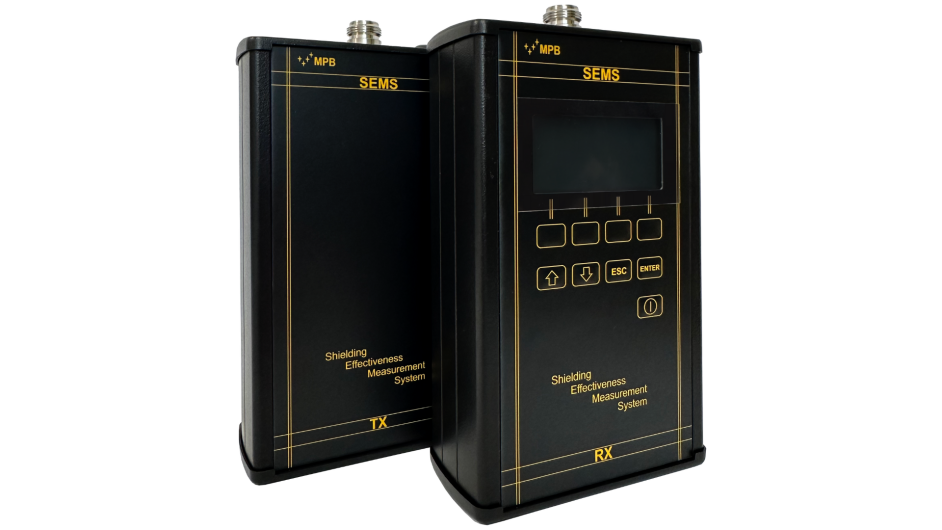
SEMS B – Shielding Effectiveness Measurement System

Category: RF Test

The SEMS B system has been specifically developed to meet the increasing global demand for reliable and accurate shielding effectiveness tests in shielded rooms, such as hospital MRI rooms, EMI/EMC chambers, military shelters and civil telecommunications cabins. Modern infrastructures require a high level of protection from external electromagnetic interference and, at the same time, strict control of emissions leaving the room. SEMS B addresses these needs by providing fast, automated and highly repeatable measurements of both electric and magnetic field attenuation.

System overview

SEMS B consists of two main units: a transmitting unit (TX) and a receiving unit (RX). Both units operate across the entire frequency range from 10 kHz to 300 MHz, enabling the evaluation of shielding performance over all the frequencies typically required by international standards. The measurement field to be tested is defined by the type of antenna used, and SEMS B supports a comprehensive antenna set to ensure full coverage of both magnetic and electric fields.

The following antennas are available:
• Two loop antennas for 10 kHz–4 MHz
• Two loop antennas for 2 MHz–128 MHz
• Two whip antennas for 1 MHz–128 MHz
• Two dipole D2 antennas for 40 MHz–300 MHz
• Two biconical antennas for 60 MHz–300 MHz
Additionally, loop antennas are available in an active version, further expanding the system’s versatility.

Unlike conventional test systems, which perform measurements only at fixed or discrete frequencies, SEMS B executes a continuous scan across the entire frequency range, dramatically improving accuracy and providing complete visibility of potential shielding weaknesses. A key innovation introduced in SEMS B is the synchronization of TX and RX units via optical fiber, ensuring immunity from external interference, improving measurement consistency and minimizing human error. This feature allows the operator to automate the entire test procedure and obtain highly repeatable results even in complex or noisy environments.

Operating principle

The functional principle of SEMS B is based on a two-step measurement method:

Phase 1 – Zero Setting

The TX unit generates an RF signal, which is radiated into free space through the selected antenna. The RX unit is positioned at a predetermined and fixed distance, receiving the signal with a similar antenna. The received level is stored as the reference level.

Phase 2 – Measurement

The RX unit is then placed inside the shielded environment, maintaining the same distance from the TX unit as before. Because the shielded room attenuates the electromagnetic signal, the RX measures a reduced signal level. The system automatically calculates the shielding effectiveness by subtracting the two values and displays the attenuation directly in dB, without any manual intervention. This method ensures high repeatability and simplicity for the operator.

Receiver (RX) architecture

Inside the RX unit, the RF signal from the receiving antenna first passes through an attenuation module, which adjusts the level to the optimal range for the subsequent stages. Next, band-selecting filters route the signal according to the frequency being measured. The conditioned signal is then converted to digital form through a high-performance ADC. A powerful RSP and DSP process the data in real time using advanced algorithms to extract accurate amplitude values, which are then displayed to the user.

Transmitter (TX) architecture

The TX unit generates the required RF signal using a Direct Digital Synthesis (DDS) source, controlled by the CPU. The CPU receives commands from the RX unit through a wireless interface, ensuring full synchronization between the two units. The generated signal is divided and amplified to reach the required output power before being fed to the transmitting antenna.

Operating modes unconnected mode

In environments where Bluetooth or optical fiber communication cannot be used, SEMS B can operate in “unconnected mode.” The operator creates a frequency list using the SEMS B PC software and uploads it directly into the RX memory. Measurements can be performed offline in a quick and simple way.

Sniffer mode

Sniffer mode is designed for technicians who need to identify weak points in the shielding of a chamber. By scanning the environment, the operator can locate leakage points or structural imperfections that may compromise the shielding effectiveness.

Calibration with CalKit

Although SEMS B does not measure absolute values, periodic verification of its linearity is essential. The system includes a dedicated CalKit, supplied with accredited calibration. The calibration procedure can be accessed directly from the RX menu. By selecting the CalKit option, the display guides the operator step-by-step through the procedure, ensuring correct execution and traceable results.

Power supply

Both TX and RX units are powered by rechargeable lithium-ion batteries. This ensures measurement independence from external power sources, eliminates ground loops and prevents unwanted interference from mains supply lines.

SEMS B Software utility

The SEMS B PC Utility software allows users to download, store and export all measurements recorded by the RX unit. Data can be exported in ASCII format, facilitating integration into customized test reports. The software also allows the creation of preprogrammed scans, including zero-setting procedures, which can be loaded into the RX’s non-volatile memory for automated operation.

SEMS B represents a modern, efficient and comprehensive solution for evaluating the shielding effectiveness of any type of shielded enclosure. With its continuous scanning capability, advanced synchronization, wide antenna support and powerful software tools, it is the ideal instrument for laboratories, hospitals, manufacturers and field technicians requiring precise and reliable EMF, EMC and RF shielding assessment.
More products by MPB Srl

Trade fair innovation
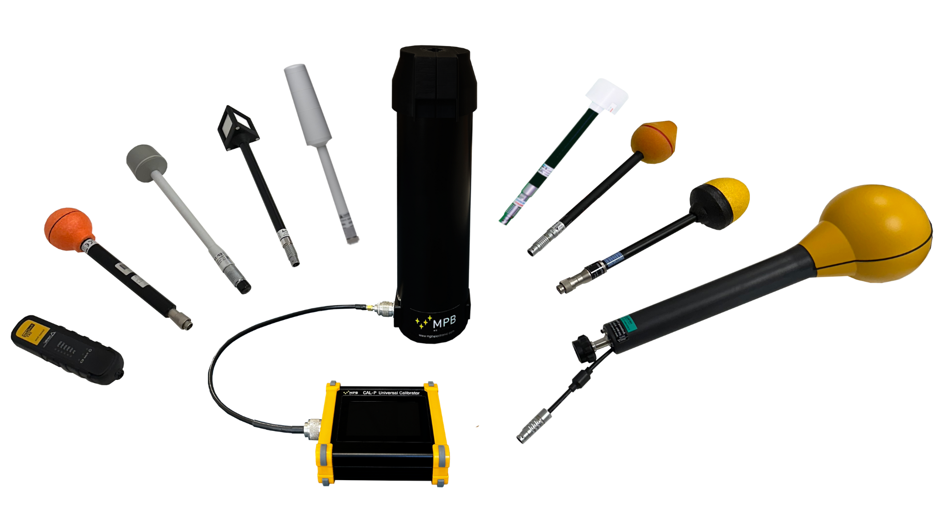
CAL-P - Universal calibrator for broadband sensors, selective antennas, personal protective equipment (PPE) for electromagnetic fields (EMF)

CAL-P - Universal calibrator for broadband sensors, selective antennas, personal protective equipment (PPE) for electromagnetic fields (EMF)

CAL-P – Universal portable calibrator for EMF Sensors, Antennas and PPE

Main Category: EMF

Description:
The CAL-P is a portable and versatile test system designed for the characterization, calibration, and verification of broadband sensors, selective antennas, and personal protective equipment (PPE) for electromagnetic fields (EMF). It enables precise measurements and independent calibration in laboratory or field environments, offering high compatibility with leading EMF instrumentation and flexible operation modes.

General Features

  • Frequency Range: 25 MHz – 4 GHz

  • Maximum Output Power: 18 dBm

  • Display: 3.5-inch color TFT touchscreen

  • I/O Interface: USB Type-C and optical fiber

  • RF Connectors: N female

  • Weight: 1.7 kg

  • Power Supply: Operator-replaceable 18650A rechargeable batteries via USB Type-C

  • Operating Time: 2 hours during active use, 5 hours on standby

Key Features: universal compatibility

CAL-P works seamlessly with major EMF measurement equipment from leading manufacturers, including Keysight, Anritsu, Rohde & Schwarz, Wavecontrol, Microrad, Aldena, and PMM/Narda.

Independent calibration and characterization

MPB provides dedicated software free of charge, enabling operators to perform jig characterization independently, without requiring external assistance. This allows the creation of custom response curves for sensors and antennas, which can be compared over time to monitor probe performance and reliability.

Modular design

The CAL-P features fully customizable supports for different sensor sizes and antenna shapes, allowing flexible adaptation to diverse testing scenarios.

Autonomous operation

The system is designed for standalone operation without the need for external control units, making it suitable for field or laboratory deployment.

Lightweight and portable

Weighing only 1.7 kg, CAL-P is easy to transport and deploy in any environment while maintaining stability and performance.

User-Friendly interface

The intuitive 3.5-inch touchscreen allows simple operation and streamlined workflow, ensuring a short learning curve for new users.

Functioning and operation

  • Manual characterization:
    Operators can independently characterize the jig manually, creating response curves for sensors and antennas. These curves can be compared over time to monitor probe performance.

  • Automated characterization:
    When the communication protocol of the measurement instrument (meter, PC, or optical repeater) is available, operators can perform automated characterization through the MPB software.

  • Remote calibration option:
    Operators can request standard reference tables directly from MPB, providing calibration at three reference frequencies to ensure consistency and traceability.

CAL-P configurations

  • Setup 1: Vertical configuration with optical fiber and repeater

  • Setup 2: Horizontal configuration with meter/analyzer

Technical specifications

  • Frequency range: 25 MHz – 4 GHz (100 kHz step)

  • Maximum power output: 18 dBm (50 Ω)

  • Display: 3.5-inch color TFT touchscreen

  • Power supply: operator-replaceable 18650A batteries, rechargeable via USB Type-C

  • Weight: 1.7 kg

  • I/O Connection: USB Type-C and optical fiber

  • RF Connectors: N female

  • Probe Lists: standard MPB lists or OEM options available on request

  • Operating Time: 2 hours active, 5 hours standby

CAL-PJ86

  • Maximum Input Power: 20 W

  • Inside Field Intensity: Up to 6150 V/m

  • Weight: 13 kg

  • Connectors: RF N female, USB Type-C (high power mode only)

  • Materials: Aluminum

Available Options:

  • CAL-PJXX customized Jig: equipped with N female connector for specialized sensors or antennas.

  • High Power Mode: custom jig with N female connector and USB Type-C port to achieve high electric field strengths.

Summary

The CAL-P is a state-of-the-art portable EMF calibrator offering unmatched versatility, precision, and autonomy for EMF testing. Its universal compatibility, modular design, and user-friendly interface make it ideal for laboratories, field engineers, and technicians requiring rapid and reliable characterization of broadband sensors, selective antennas, and personal protective equipment. With both manual and automated calibration options, the CAL-P ensures high repeatability, traceability, and operational efficiency in any measurement scenario.

Trade fair innovation
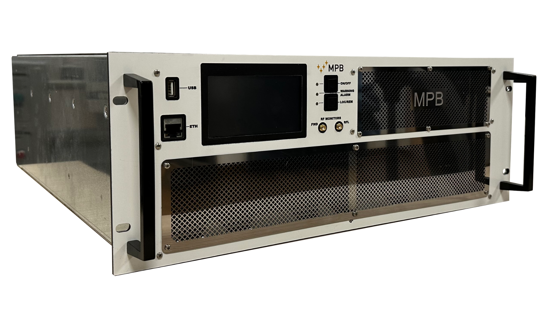
PA27-1000/500_High-Power RF Amplifiers for EMI/EMC Applications

PA27-1000/500_High-Power RF Amplifiers for EMI/EMC Applications

HIGHPOWER RF AMPLIFIER | ISM APPLICATIONS – PA27-1000/500

The PA-271000/500 is a medium- to high-power RF amplifier specifically designed for ISM (Industrial, Scientific, Medical) applications in the frequency range of 27 MHz to 1000 MHz. It delivers outstanding output power, linearity, and reliability, making it ideal for demanding EMI/EMC test applications in both laboratory and industrial environments.

This amplifier uses state-of-the-art solid-state technology to achieve high performance, robust operation, and long-term reliability. The unit operates in Class AB, combining high efficiency with excellent linearity. It integrates modern user interfaces and telemetry features to monitor operational parameters and ensure safe and efficient operation.

The PA27-1000/500 is particularly suited for EMI test applications, including RF conducted immunity and radiated immunity tests, according to international standards such as IEC 61000-4-6 and IEC 61000-4-3. Its rugged design and comprehensive monitoring capabilities make it ideal for use in industrial, scientific, medical, and research facilities requiring high-performance RF testing.

Main features

  • High ruggedness for industrial environments

  • Integrated 3.5-inch touchscreen display for intuitive operation

  • Built-in telemetry for real-time monitoring of:

    • Forward and reflected RF power

    • DC voltage

    • Internal temperature

    • Alarm status

  • Self-protection features against:

    • Abnormal temperature conditions

    • Input overdrive

    • Excessive reflected power and current absorption

  • Class AB operation for high efficiency and linearity

  • Optional automatic level control (ALC) for stable output

  • Flexible remote control via USB Type-C and RJ45/SNMP

User interface and controls

The amplifier features a user-friendly interface with both local and remote operation modes:

  • TX ON/OFF: Start or stop the amplifier quickly

  • LOC/REM: Switch between local and remote operation

  • Touchscreen display: Full system monitoring and control

  • USB Type-C port: Firmware updates, configuration, and software interface

  • RJ45 port: WEB or SNMP interface for remote monitoring

  • SMA female connectors: Forward and reflected power monitoring (0 dBm max)

  • Directional coupler: Included for precise measurement and monitoring

General Technical Specifications

  • Frequency Range: 27 - 1000 MHz
  • Output power @1 dBc: 500 W
  • AC Input: Pluggable terminal blocks, 5 positions, 7.62 mm
  • RF Connectors: N female for input and output

Mechanical Specifications

  • RF Input Connector: N female

  • RF Output Connector: N female

  • Forward Monitoring: SMA female

  • Reflected Monitoring: SMA female

  • Dimensions (L x W x H): 483 x 613 x 177 mm

  • Weight: 35 kg

  • Cooling: Forced air cooling (front intake, rear exhaust)

Environmental Specifications

  • Operating Temperature Range: 0 °C to +45 °C

  • Storage Temperature Range: -20 °C to +85 °C

  • Relative Humidity: Up to 95% (non-condensing)

  • Operating Altitude: Up to 2000 m above sea level

Optional Features

  • ALC (Automatic Level Control) for precise power regulation

  • SNMP management support for integration with networked monitoring systems

  • SCP protocol support for automated test control

  • ModBus interface for industrial communication and automation

Safety and protection features

The amplifier integrates multiple protection mechanisms to ensure safe operation under demanding conditions:

  • Protection against excessive internal temperatures

  • Input overdrive protection

  • Protection from excessive reflecte